
State-of-the-Art Tools
Klippel introduced the Large Signal Identification (LIS) and Linear Parameter Measurement (LPM) software tools 25 years ago to measure linear and nonlinear loudspeaker parameters, in conjunction with Klippel analyzer hardware. The LPM software module was designed for small-amplitude measurements using a lumped parameter model based on and extending the work of Neville Thiele and Richard Small.
The LSI module — and its successors, LSI2 and LSI3 — employed a lumped parameter model as well. However, to remain valid at large amplitudes where nonlinearities dominate, the model was extended with nonlinear elements that depend on voice coil displacement, velocity, current, and other state variables. To this day, LSI remains the only commercially available system for measuring the nonlinear loudspeaker parameters.
Both LPM and LSI software modules have become indispensable tools for loudspeaker development in R&D labs worldwide. However, several limitations have become apparent over time. For example, LPM could only identify parameters in free-air or closed-box configurations. The inductance model used in LPM and LSI lacked sufficient accuracy if the frequency bandwidth was set too high. Moreover, because LSI used noise signals and identified the parameters in the time-domain, measurement durations were long (10 minutes and more), slowing down the evaluation process when comparing multiple loudspeakers. Long test durations also caused excessive voice coil heating, necessitating reduced test levels to prevent damage.
Additionally, the random noise stimulus prevented directly specifying a target voice coil displacement for the protection system. In LSI, all signal processing was handled by an embedded processor in the Klippel Analyzer hardware, and only a limited set of diagnostic data was uploaded to the PC. This lack of transparency sometimes hindered effective troubleshooting.
Introducing FLSI
To address these challenges and advance the state of loudspeaker parameter measurement, Klippel has developed the Fast Large Signal Identification (FLSI) measurement tool — a new measurement software module designed to replace both LPM and LSI. FLSI delivers faster measurements, improved model accuracy, better automation, and significantly enhanced diagnostic capabilities.
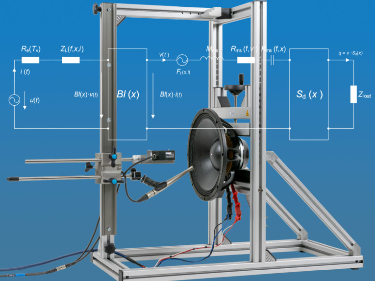
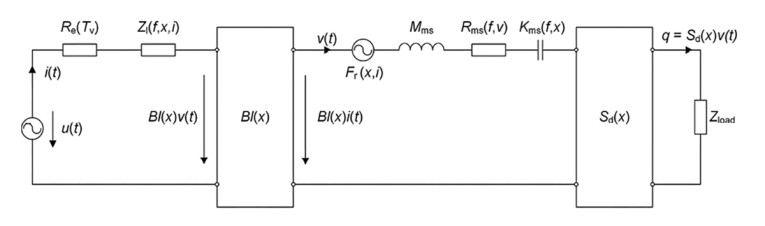
As with LSI, FLSI uses a fully dynamic measurement technique that has proven reliable — and superior to static and semi-static methods — over many years. The device under test is excited by a stimulus. Voltage, current, and as an option, sound pressure and displacement are measured. Using linear and nonlinear system identification algorithms that minimize the error between measured and predicted state signals, the lumped parameters of an electro-mechanical equivalent circuit are estimated, as shown in Figure 1. The structure of this model reflects the transducer principle and the fundamental physical mechanisms within the loudspeaker. Its parameters are closely related to the loudspeaker’s operating principle, specific design, material properties, and assembly techniques.
In addition to modeling the transducer’s behavior, FLSI also identifies parameters and nonlinear distortion contributions from the enclosure — such as the port nonlinearity in bass reflex systems.
These parameters can also be used to create initial parameters for the Klippel Controlled Sound (KCS) solution — a real-time control algorithm that protects the transducer from overload and actively reduces distortion.
FLSI automates the entire measurement process, capturing both linear and nonlinear parameters in a single measurement, eliminating the need to import Bl(x=0) from LPM, as was required by the original LSI. The maximum displacement limit can now be specified with new protection metrics: a target displacement is measured via a laser, while Rub & Buzz is identified with a microphone. These measures prevent voice coil damage due to overload, such as bottoming and voice coil rubbing, to protect valuable prototypes. When measuring multiple samples of the same model, users can skip the set-up phase and proceed directly to the final stimulus level, further speeding up the process. Measurement times as short as 20 seconds are achievable.
In contrast to the original LSI’s random noise signal, FLSI uses a multi-tone stimulus. This signal excites many frequencies simultaneously across a wide bandwidth, providing several advantages for both small- and large-signal measurements; it enables shorter measurement times; improves test repeatability and reproducibility due to its deterministic nature; and lowers amplifier peak voltage requirements because lower crest factors can be realized. Additionally, the stimulus is shaped to resemble typical audio program material in terms of bandwidth and amplitude distribution, while minimizing overall power requirements.
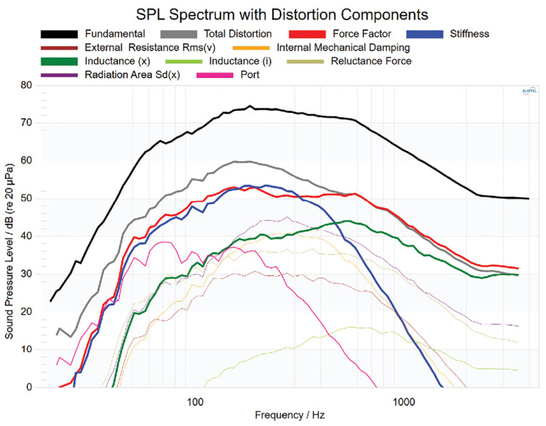
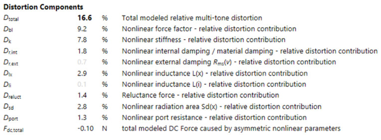
A major benefit of this approach is the easy separation of the fundamental and the nonlinear distortion components. In the small-signal measurements, this allows calculation of the signal-to-distortion ratio and to automatically adjust the stimulus parameters (e.g., bandwidth, amplitude, number of averages). In the large-signal measurement, it enables the calculation of individual distortion contributions from each nonlinearity, referenced to the fundamental component. This distortion analysis provides deep diagnostic insight, revealing both dominant and negligible sources of nonlinear distortion. Contrary to the LSI’s distortion analysis — which displays peak distortion values of a limited set of nonlinearities — FLSI visualizes spectral contributions (Figure 2) and relative total RMS values for each distortion source, as shown in Figure 3.
Diagnostics and Key Parameters
Force Factor: A key source of distortion is the electromechanical transduction mechanism, characterized by the force factor Bl(x). This parameter, which converts electrical current into mechanical force, is not constant — it can vary significantly with voice coil displacement. As the coil moves out of the magnetic gap, the force factor decreases, introducing harmonic distortion at low frequencies and intermodulation distortion across the entire frequency range (Figure 2).
An additional benefit of analyzing the Bl(x) curve is the ability to assess whether the voice coil is properly centered within the magnetic field, and to determine any necessary adjustments in production. The maximum magnetic flux density does not always coincide with the geometric center of the gap. Shifting the coil to its optimal position maximizes performance without adding any additional material costs. In Figure 4, a voice coil shift of approximately 0.75mm toward the backplate is recommended.

Nonlinear Mechanical Resonator: Once the mechanical force is generated, it acts on a mechanical resonator — a mass-spring-damper system consisting of the diaphragm, suspension (spider and surround), and air load. The stiffness and damping of the suspension are nonlinear and vary with displacement, velocity, time, frequency, and force due to factors such as mechanical creep, mechanical hysteresis, air leakage, turbulent airflow, and aging. These effects generate both linear and nonlinear distortion components, which may evolve over time due to usage or changing environmental conditions. They primarily produce harmonic distortion at low frequencies, where displacement and velocity are high (Figure 2).
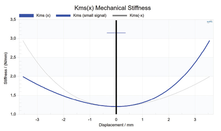
FLSI also allows engineers to compare the mechanical stiffness and resistance values at low and high amplitudes. For example, the mechanical stiffness can change significantly with time. In Figure 5, the stiffness at the voice coil rest position varied by nearly a factor of three between the small- and large-signal measurements, a difference that must be considered for proper alignment and mechanical protection. FLSI provides distortion spectra for all these effects — stiffness, external resistance (due to airflow), and internal damping (mechanical hysteresis in the suspension materials) — and displays the nonlinear parameters Kms(x) and Rms(v). It also provides frequency-dependent stiffness curves in both the small- and large-signal domain, enabling an analysis of creep and air leakage in closed-box systems.
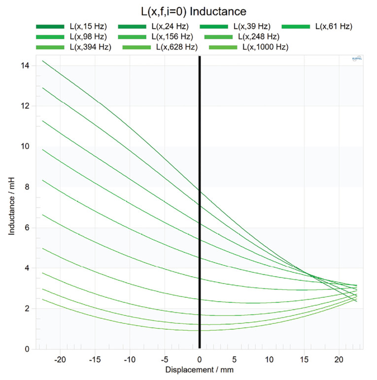
The previous LSI algorithm identified a single nonlinear inductance curve, which represented the effective inductance over the entire excited bandwidth. However, this approximation becomes inaccurate when shorting material is present in the transducer motor and when the transducer operates over a wide frequency range. To address this, the nonlinear inductance model in FLSI was extended to a frequency-dependent nonlinear inductance, L(f, x, i). In Figure 6, the shape of the nonlinear inductance curve highly depends on the frequency.
In addition to the high-frequency intermodulation distortion caused by the nonlinear inductance, the non-uniform distribution of the alternating magnetic flux along the moving axis of the voice coil generates a reluctance force. This creates additional distortion in the audio band, which is visualized in the distortion spectrum, and creates a DC displacement.
The total DC force resulting from all the nonlinearities combined is also calculated and provides insight into asymmetries in the loudspeaker’s parameters. If the resulting force becomes too high, it may be necessary to increase the mechanical stiffness of the suspension or to reduce asymmetries in other parameters.
Nonlinear Effective Radiation Area: As the diaphragm moves, it deforms the surround. If the surround makes up a significant portion of the total radiating surface, this deformation modulates the effective radiating area Sd(x) as a function of displacement x. This effect is particularly relevant in compact transducers, such as smartphone speakers, and long-throw woofers. An asymmetric surround geometry (e.g., a single roll) primarily introduces second-order intermodulation distortion, as well as some second-order harmonic distortion at low frequencies. The relative multi-tone distortion can reach 10% or more and is visualized in the distortion spectrum (Figure 2). Because the Sd(x) distortion is not observable in the electrical domain, a microphone is required for its identification.
Loudspeaker System Measurements: In addition to free-air measurements, measuring loudspeaker parameters with the transducer mounted in an enclosure similar to the final product is highly recommended. The linear enclosure parameters, such as port resonance frequency and Q-factor, cannot only be used for validating simulation results but also support accurate system alignment.
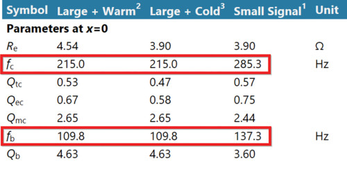
It is recommended to compare the parameters, especially the system resonance frequency fb of vented and passive radiator systems, in the small and the large signal domain, as they can change significantly: For example, the port characteristics may change at high levels if the port mouth is located too close to a wall. Passive radiators feature a suspension system similar to that of the main transducer, which can vary by a factor of two and more under large-signal conditions, affecting the system resonance frequency fb as shown in Figure 7. This affects the system alignment and increases the passive radiator displacement.
Beyond the transducer itself, nonlinearities arise in enclosures such as vented boxes and passive radiator systems due to airflow in and around the port (e.g., turbulent flow and vortex shedding) and from the suspension of the passive radiator. These effects introduce nonlinear distortion and cause an unwanted voice coil DC displacement if the nonlinearities exhibit asymmetric behavior. The distortion spectra in Figure 2 illustrates the impact of the identified acoustical load nonlinearities. FLSI supports the measurement of closed, vented, fourth-order bandpass, and passive radiator loudspeaker systems.
Thermal Model: As an electrical current flows through the voice coil, it generates heat, increasing the coil’s resistance. This change affects the system’s input/output behavior, reducing both voltage sensitivity and power efficiency. If the temperature exceeds the voice coil’s maximum rated limit, it can cause permanent damage.
The transducer’s power handling capability can be improved by optimizing the coil’s self-cooling performance through convection cooling. The effectiveness of this depends, for example, on the coil’s total surface area, the air velocity around the coil, and the size of the ventilation hole in the pole piece. However, a trade-off is required when optimizing the cooling performance: high velocities may lead to audible airflow noise and can introduce nonlinear Rms(v) distortion, even in woofers.
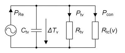
FLSI identifies the short-term thermal model parameters of the voice coil as shown in Figure 8. It includes the thermal capacitance Ctv — which mainly depends on the coil’s mass and contributes to the heating and cooling time constants — and two separate thermal resistances representing thermal conduction to nearby motor parts (Rtv) and convection cooling (Rtc(v)). These parameters are highly valuable for estimating the short-term power handling capability and for optimizing the cooling performance. They serve as objective metrics when evaluating different voice coil and motor geometries, or alternative voice coil former materials.
Summary
The FLSI measurement enables engineers to analyze and comprehend the relevant loudspeaker nonlinearities on a new level. By automatically identifying the linear and nonlinear parameters, it provides deep insight into the dominant sources of distortion. This understanding empowers targeted improvements — whether in motor design, suspension geometry, material selection, or thermal management.
Nonlinear distortion in loudspeakers is typically not caused by a single source, but by a complex interaction of different mechanisms across multiple physical domains. With accurate modeling and considerate engineering, these effects can be understood, minimized, and — in some cases — even exploited to enhance performance.
As the FLSI development continues, Klippel is placing a strong emphasis on expanding the diagnostic capabilities of the measurement system to better support the interpretation of results, suggest improvements, and highlight design weaknesses. Overall, FLSI represents a significant leap forward in loudspeaker measurement and modeling capabilities. It is currently available as pre-release software. Please contact Klippel if you are interested in becoming a tester. VC
This article was originally published in Voice Coil, August 2025
About Klippel
Klippel provides unique test equipment for electro-acoustical transducers and audio systems. Founded in 1997 by Dr. Wolfgang Klippel, the techniques developed for control and measurement systems of loudspeakers and other transducers are the result of more than 30 years of fundamental research. This provides more accurate physical models of loudspeakers, microspeakers, and headphones valid for both small and large amplitudes. The focus is on the root causes of signal distortion and defects and giving practical indications for improvements in design and manufacturing of audio products. www.klippel.de
 About the Author
Jonathan Gerbet was born in Greiz, Germany, in 1988. He studied Electrical Engineering at Dresden University of Technology and joined Klippel GmbH in 2015 as a Research and Development Engineer. His work focuses on loudspeaker modeling, simulation, and measurement, with a particular emphasis on linear and nonlinear system identification and active control techniques.