
Microphones are straightforward yet important components. Simply put: Microphones feature a transducer that converts pressure variations in the air into an electrical output, typically a voltage that can be recorded, amplified, transmitted, or analyzed, among other things.
First developed more than 150 years ago, microphone transducer principles have evolved over time. Remarkably, several of these principles continue to coexist across different industries today. In professional audio, both dynamic and condenser microphones have strong points. However, electret condenser microphones (ECMs) are preferred for a wide range of applications. This is largely due to the miniaturization of the transducer, which makes them ideal for film, broadcasting, live performance, communication, surveillance, and more.
Despite their small footprint, condenser microphones are recognized for their frequency response, dynamic range and, to a certain extent, low noise and distortion. Achieving a dynamic range above 100dB is not unusual, but it must be balanced against various inherent limitations.
Noise
All microphones produce some level of noise because of the current running through the circuitry. Thermal noise is also an issue as increased temperatures cause higher noise. Additionally, noise is caused by the presence of air molecules inside the microphone capsule bombarding the diaphragm and generating acoustic self-noise. Ultimately, self-noise determines the “bottom” of a microphone’s dynamic range.
The basic nature of the noise in microphones is referred to as white noise, which derives from comparing audio to light. Just as white light encompasses the entire spectrum of visible light, white noise contains an equal amount of energy at all audible frequencies.
While the signal contains no discernible tones, the character of the noise may differ depending on the frequency distribution. When amplified, it sometimes sounds smooth and at other times, it sounds crackly. Additionally, depending on the type of microphone and design, the noise sometimes sounds darker or lighter.
How to Specify Noise
Self-noise is expressed as an equivalent sound pressure level (SPL). Example: A microphone with a self-noise of 22dB(A) — “A” denotes A-weighting — produces the same output as a sound source at 22dB(A) SPL. If the sensitivity is 20mV/Pa, the microphone output would be approximately 5μV(A), even if there is no sound source (Figure 1).
Alternatively, noise can be measured using peak values with a different weighting filter (for instance, CCIR weighting). However, the A-weighted noise level serves as the baseline for calculating a microphone’s dynamic range. All condenser microphones implement an impedance converter, which functions as an internal preamp. While not very complex, the design is vital to the overall performance of the microphone.
Distortion in Microphones
Distortion refers to any alteration of an audio signal’s waveform as it passes from an input to an output. It can result from nonlinearities (nonlinear distortion) or changes in magnitude and phase in a linear system (linear distortion).
While intentional modifications (e.g., equalization or bandwidth limitations) technically cause distortion, it is unintended distortion caused by system limitations and nonlinear behavior that impacts the perceived sound quality. Even air impacts distortion in extreme conditions. At very high SPLs, nonlinearities arise because the positive waveforms travel faster than negative ones. For instance, this means that a pure tone will transform into a sawtooth waveform when propagating in air at extremely loud SPLs, which introduces new harmonic components.
Diaphragms on the Move
A key component of a condenser microphone is the diaphragm, which is positioned in front of a back plate, separated by approximately 10μm to 100μm. At high SPL, there is a limit to the diaphragm’s movement, both when pushed in toward the back plate and also with regard to how “stretchable” it is in either direction.
As mentioned, condenser microphones also require an electronic interstage that converts the high impedance of the transducer into a relatively low impedance, for longer cable runs. Miniature microphones are also supplied by an unbalanced power supply. These electronic designs can cause nonlinear behavior. Achieving a wide dynamic range with minimal distortion requires careful attention to the acoustical, mechanical, and electronic design aspects.

How to Specify Distortion
According to the International Electrotechnical Commission (IEC) standards [1, 2], the amplitude nonlinearity is expressed by three measures: total harmonic distortion (THD), nth-order distortion, and second-order difference frequency distortion.
THD: A pure sinewave contains only one frequency. When distorted (typically by clipping), it produces additional frequencies at integer multiples of the original tone, known as harmonics. For example, a 1kHz signal might produce harmonics at 2kHz, 3kHz, 4kHz, and more, usually at decreasing levels. Symmetrical clipping tends to produce primarily odd harmonics generated: third, fifth, seventh, and so forth.
THD is defined as the ratio of the Root Mean Square (RMS) sum of the harmonic components in the output voltage to the total RMS output voltage of the microphone [2], which is typically expressed as a percentage. As a rule of thumb, THD should ideally be kept below 1%, meaning the unwanted frequency components are at least 40dB below the fundamental frequency. THD is the portion of harmonics that occur due to nonlinearity, for instance clipping (Figure 2).
In practice, measuring THD acoustically requires the generation of very loud SPLs, which is a challenge not easy to circumvent since loudspeakers exhibit typically greater levels of distortion than microphones. In any case, the measured THD can be influenced by the system’s noise floor, particularly when the microphone under test is still very linear at high SPLs. Therefore, the result is often denoted as THD+N (total harmonic distortion plus noise).
Distortion of the nth order: In principle, this is the same as THD, except that harmonics are individually measured and quantified. The third harmonic is sometimes of particular interest, especially in cases of symmetrical clipping, because it represents the highest level of all harmonics generated.
Difference frequency distortion: For this measurement, two different-frequency pure tones are applied at identical levels. The IEC defines frequency spacing as 80Hz (e.g., between 1000Hz and 1080Hz), though measurements can also be conducted over a broader frequency range, if needed. As a result, the sum and the difference of the distortion of the original frequencies are generated. These frequency components are measured and quantified as a percentage of the fundamental frequencies.
It must be noted that it’s absolutely fine to apply a standardized methodology for quantifying distortion. However, the standards only consider a small selection of possible forms of distortion. In reality, signals are far more complex, and so are the distortion components.

What Is Audible?
To determine what is audible, we must look to psychoacoustic research [3, 4, 5]. Detailed here are some phenomena that influence perceived sound quality.
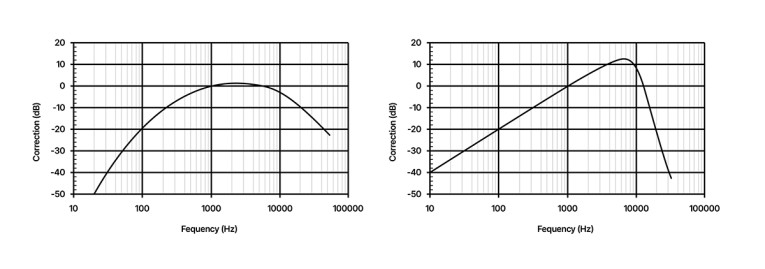
Threshold of hearing: The human hearing system has a naturally lower limit, which varies with frequency. At low frequencies, the threshold is rather high, while around 2kHz to 4kHz, the threshold is low (Figure 3).
Masking: When the ear is exposed to sound energy in a specific frequency range, surrounding frequencies are masked. This masking primarily works toward higher frequencies. As a result,
the primary sound energy shadows some of the harmonic components generated by distortion, which causes them to become inaudible (Figure 4).
By contrast, the frequency components below the masking frequencies become the most audible. This is also related to the fact that some tones are not necessarily musical and are therefore perceived as more annoying. In addition to the distortion caused by audio equipment, the ear itself generates distortion, which typically occurs at high levels.
In general, it is accepted that distortion below 1% is regarded as inaudible at normal listening levels. Some manufacturers state the minimum SPL to achieve 1% THD, others 0.5% THD.

What Microphones with CORE+ by DPA Can Do
DPA Microphones continually pushes the boundaries of technology because innovation is the driving force that brings the industry forward. Before CORE+ by DPA was introduced, the sonic quality of DPA microphones was already high, but research showed that there was still room for improvement.
In recent years, the entire pro audio sound chain has improved — from the microphone at the beginning all the way to the speakers at the end. Innovations in technology mean that the sound that reaches the public’s ears is generally of much higher quality. This is due, in large part, to the improvements in wireless transmitters and the digitization of wireless systems. In fact, today’s high-quality wireless transmitters and receivers are so good they can handle dynamic ranges higher than some professional microphones can deliver.
CORE+, and the earlier developed CORE technology, improves how the impedance converter (preamplifier) interprets the minuscule diaphragm movement within the capsule and converts it into an electrical signal. This has made it possible to transform the sound without changing the legacy characteristics of DPA’s miniature microphones.

Field-Effect Transistors (FET) in CORE by DPA Microphones
Microphone elements produce a signal depending on the acoustic input, which cannot drive long cables and standard post-processing systems. Instead, a buffer is needed. The solution is using a field-effect transistor (FET), which is the most straightforward circuitry available inside the miniature microphone housing (Figure 5). The FET exhibits the necessary, extremely high input impedance and relatively low output impedance, while the audio signal from the electret element controls the current through the FET.
Controlling the current through a FET is a little like squeezing a water hose: if you tighten the grip, less water passes; if you press it too hard, the water stops running (for FETs, this is called the “cut-off mode”). The simple FET circuitry works relatively well if the cut-off mode is not reached. However, it has two disadvantages:
• The current through the FET (the microphone’s output) is not a completely linear function of the signal input. The result is a nonlinear dynamic range and some distortion, which vary by brand and model. [6].
• Some transmitters contain a built-in correction network for the linearization of the FET, but most do not.
• The original CORE technology eliminates the nonlinearity caused by electronics, which has led to a dramatic reduction of distortion. For distortion reduction at all levels, the 1% THD is attained at a 14dB higher level, extending with the same amount of dynamic range.

Polarity
Using a simple FET as the impedance converter has an issue: When the sound pressure on the microphone diaphragm increases (positive pressure), output decreases (goes negative) due to the bias voltage’s polarity. However, audio standards state that microphones should produce a positive voltage in response to positive pressure at the front of the diaphragm. Some manufacturers correct this by reversing the transmission system's polarity [7].
With the original CORE by DPA technology, the performance of DPA miniature and subminiature microphones was improved through these features (Figure 6):
• Positive output for positive-going sound pressure (i.e., in-phase).
• Fully compensated electronics provide the lowest distortion possible at all levels (until CORE+).
• Each microphone is trimmed to maximum performance and does not need a specific brand transmitter for better performance.
• By miniaturizing the advanced electronic circuitry, CORE by DPA technology can be contained even in the small 3mm capsule housing of the subminiature microphones.


Introducing CORE+ by DPA
When CORE+ by DPA was introduced, the focus turned to analyzing the nature of diaphragm distortion caused by nonlinear displacement, which provided an opportunity for correction. Diaphragm displacement is very subtle. At 94dB SPL (1Pa), the air particle displacement is less than 1μm (Figure 7). The diaphragm is slightly reluctant to follow due to its acoustic impedance, so displacement is just a fraction of the particle displacement. The effect of the correction of the nonlinearities results in an unmeasurable distortion from the level of the self-noise up to a few decibels below the clipping point.
CORE technology enhances performance in a conventional way, essentially shifting the THD curve toward higher SPLs by 14dB, which directly enhances the dynamic range of the microphone by the same amount (Figure 8). CORE+ goes way beyond convention, removing any trace of distortion from the microphone output, until the clipping point is reached (Figure 9).
While the performance of a DPA 4061 CORE microphone is remarkable considering the small dimensions of the capsule, the output spectrum of the 4061 with CORE+ remains distortion-free even at 133dB SPL. In other words, THD calculations of CORE+ microphones are the result of the ratio between the energy of the system’s noise floor at the harmonic components and the total energy of the output signal mainly dominated by the fundamental component. This is why the THD curve of CORE+ microphones is flat before the microphones reach a clipping point.
Measuring only the distortion of the microphone in a test environment and not the one created by the sound systems at high SPLs is a complicated task, since a microphone is typically more linear. That is why the noise floor observed in the output spectrum of the microphones features the actual signal-to-noise ratio of the system in combination with the signal processing required to remove the nonlinearities of the measurement system.

That Said...
The microphone may work perfectly when the supplied bias voltage meets the requirement. It should be noted that the magnitude of the bias voltage determines the possible level of the audio signal, which can never exceed the operating voltage. To achieve an audio signal of a given amplitude, a sufficient operating bias voltage (typically 5V to 7V) should be available.
A microphone with DC voltage that is too low might result in asymmetrical clipping of the audio signal above a certain level (Figure 10). The result: The lower the DC voltage, the more distortion at increased levels. If the available bias voltage is 3V or 4V, the microphone still works, but the acoustical input must be reduced and kept 6dB to 10dB below maximum SPL to avoid distortion.

Conclusion
CORE+ is DPA’s latest patent-pending technological invention and extends DPA's CORE technology. Where CORE by DPA provides a linearization of the electronics, CORE+ linearizes the diaphragm output at the SPL range close to the clipping point. The effect is an unmeasurable THD in the upper part of the dynamic range. CORE+ does not raise the maximum SPL but makes the upper range as clean as already found at lower ranges. aX
This article was originally published in audioXpress, July 2025.
References
[1] IEC 60.268 Sound System Equipment, part 2: Explanation of general terms and calculation methods.
[2] IEC 60.268 Sound System Equipment, part 4: Microphones.
[3] E. R. Geddes and L. W. Lee, “Auditory Perception of Nonlinear Distortion — Theory,” Audio Engineering Society (AES) 115th Convention, Paper 5890, 2003.
[4] ] E. R. Geddes and L. W. Lee, “Auditory Perception of Nonlinear Distortion,” Audio Engineering Society (AES) 115th Convention, Paper 5891, 2003.
[5] F. E. Toole, Sound Reproduction - The Acoustics of Loudspeakers and Rooms, Focal Press, 2008, ISBN 978-0-240-520094.
[6] DPA Microphones Mic University, “How to ensure optimum performance of miniature DPA microphones for wireless,” DPA Microphones, 2025.
www.dpamicrophones.com/mic-university/audio-production/how-to-ensure-optimum-performance-of-miniature-dpa-mics-for-wireless
[7] DPA Microphones Mic University, “The polarity of wireless belt-pack systems,” DPA Microphones, 2025.
www.dpamicrophones.com/mic-university/technology/the-polarity-of-wireless-belt-pack-systems
 About the Authors
Eddy Bøgh Brixen received his education in electronic engineering from Danish Broadcasting Corp., the Copenhagen Engineering College and the Technical University of Denmark. He consults in room acoustics, electro-acoustic design, and audio forensics. He is a consultant with — and the owner of — EBB-consult, an Audio Specialist with DPA Microphones, and an Associate Professor with the Danish National School of Performing Arts. Eddy is the author of several textbooks on audio of which Audio Metering, published by Focal Press, is one.
 Originally from Barcelona, Spain, Toni Torras Rosell is a member of DPA Microphones' talented R&D department. After receiving his telecommunications engineering degree in Spain, he moved to Denmark to finish a master’s in engineering acoustics (and later his industrial PhD) at Denmark’s Technical University. Toni has a strong background in developing theoretical acoustical models.