

Loudspeaker Enclosure with a Sealed Acoustic Suspension Chamber
Patent/Publication Number: US20180027321A1
Patent/Publication Number: US10362386B2
Inventor(s): Rohan Jaguste (Johanneshov, Stockholm)
Assignee: Keyofd AB (Johanneshov, Stockholm)
Reassigned in 2020 to: De Profundis AB
Filed: February 12, 2016
Published: January 25, 2018
Granted in US: July 23, 2019
Number of Claims: 16
Number of Drawings: 8
Abstract from Patent
The present invention relates to a loudspeaker enclosure housing a sealed acoustic suspension chamber. In the sealed acoustic suspension chamber are arranged a driver and a passive acoustic diaphragm on opposite sides of an inner surface of the sealed acoustic suspension chamber. The loudspeaker enclosure also houses a first band-pass chamber connected to the sealed acoustic suspension chamber by the passive acoustic diaphragm.
Independent Claims
1. A loudspeaker enclosure housing a sealed acoustic suspension chamber, the suspension chamber comprising a driver and a passive acoustic diaphragm being arranged on opposite sides of an inner surface of the sealed acoustic suspension chamber, wherein the loudspeaker enclosure also houses a first band-pass chamber connected to the sealed acoustic suspension chamber by the passive acoustic diaphragm, and the inner surface of the sealed acoustic suspension chamber is continuously curved.
Reviewer Comments
Disclosed is a new form of full-range (non-bandpass), multi-chamber, multi-tuned, bass-reflex enclosure system. One significant advantage of a standard, bass reflex enclosure with a single Helmholtz tuning frequency (FB) is that at FB, the active driver voice-coil/diaphragm excursion is dramatically reduced for a given system sound pressure level (SPL), allowing significantly greater output for a given excursion for frequencies in the range of 0.85 × FB to 1.8 × FB, (approximately one octave) as compared to a standard acoustic suspension based enclosure system.
Very shortly after the original 1934 Albert Thuras/Bell Labs patent (US 1,869,178, “Sound Translating Device”) was published, disclosing the invention of the first well-characterized, single-tuned bass-reflex system, loudspeaker practitioners started experimenting with multi-tuned systems. One of the advantageous goals of these systems was to have a second, tuning frequency (FB2) at approximately two times FB, to provide a second excursion minimum, theoretically reducing the cubic volume displacement requirements (and therefore increasing large signal output capability) over an even wider frequency range than a standard single-tuned bass reflex system.
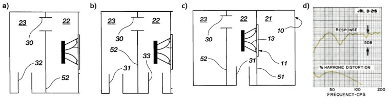
As shown in Figure 1, there are three primary, dual-tuned, non-bandpass architectures. One of the earliest, and most prominent, dual-tuned systems (shown in Prior Art, Figure 1a), was developed by Peter J. Walker of QUAD Acoustical Manufacturing Corp. (He is well known for his development of the ground-breaking QUAD Electrostatic Loudspeaker in the mid-1950s). This dual-tuned reflex was developed and marketed as the QUAD Corner Ribbon Loudspeaker starting in 1950. D.E.L Shorter, of the British Broadcasting Corp., disclosed a further advancement of this configuration in the 1953 British patent, (Patent #686,671, “Improvements in and relating to Loudspeakers”). More recently, this version of the dual-tuned reflex has become popular in Japan, as exemplified by the Fostex FE127E ‘Double Bass Reflex’ enclosure system, tuned to 53 Hz and 120 Hz.
In the December 1961 issue of Electronics World Magazine, George L. Augspurger wrote an article titled “Double Chamber Speaker Enclosure,” in which he was the first to disclose the three-port, dual-chamber bass reflex system (see Prior Art, Figure 1b). As he stated, the development was an experiment to see how low an 8” woofer could be used, while still maintaining adequate large signal capability. Augspurger found that by tuning the enclosure to 35 Hz and 70 Hz he could achieve good response to below 35 Hz while gaining a significant improvement in low-frequency SPL across the low-frequency band with very low distortion.
Unfortunately, it was found that the dual-tuned system was not the complete “Holy Grail” that was hoped for. Augspurger discovered that the system exhibited a dip in the response of about 3 dB just below the upper tuning frequency (see Figure 1d). While at the time, he speculated that the dip could be eliminated with further experimentation with chamber volumes and port acoustic mass values, years later, he admitted that he never could eliminate the problem and it turns out, to be a characteristic that is endemic to all forms of dual tuned non-bandpass, bass reflex systems, including all three of the layouts shown in Figures 1a–c.
Whether referring to the two- or three-port versions, when the frequency falls below the upper tuning frequency as the active driver excursion starts increasing again and before the lower tuning frequency starts to take effect, the phase of the active driver’s direct frontal output interacts with “leakage” through the port from the active driver’s phase reversed, rear output over a narrow band of frequencies.
The third format, shown in Figure 1c, was disclosed in E. J. Jordan’s 1963 book, Loudspeakers, as shown on page 160. The first patent on this configuration appears to be that of Edwin A. Hance, detailed in US Patent 3,690,405, “Loudspeaker System Having Bass Response Range Below System Resonance” which was granted September 12, 1972.
This last dual-tuned format was often used to compensate for under-damped systems or, as in the version developed by Bose, to minimize internal standing waves, as disclosed in its US Patent 7,269,270, “Standing Wave Reducing” by inventors Eric J. Freeman and Timothy Holl. While this configuration can be optimized for fairly smooth response, in most alignments it can have an even larger problem with the amplitude dip than the first two formats.
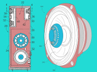
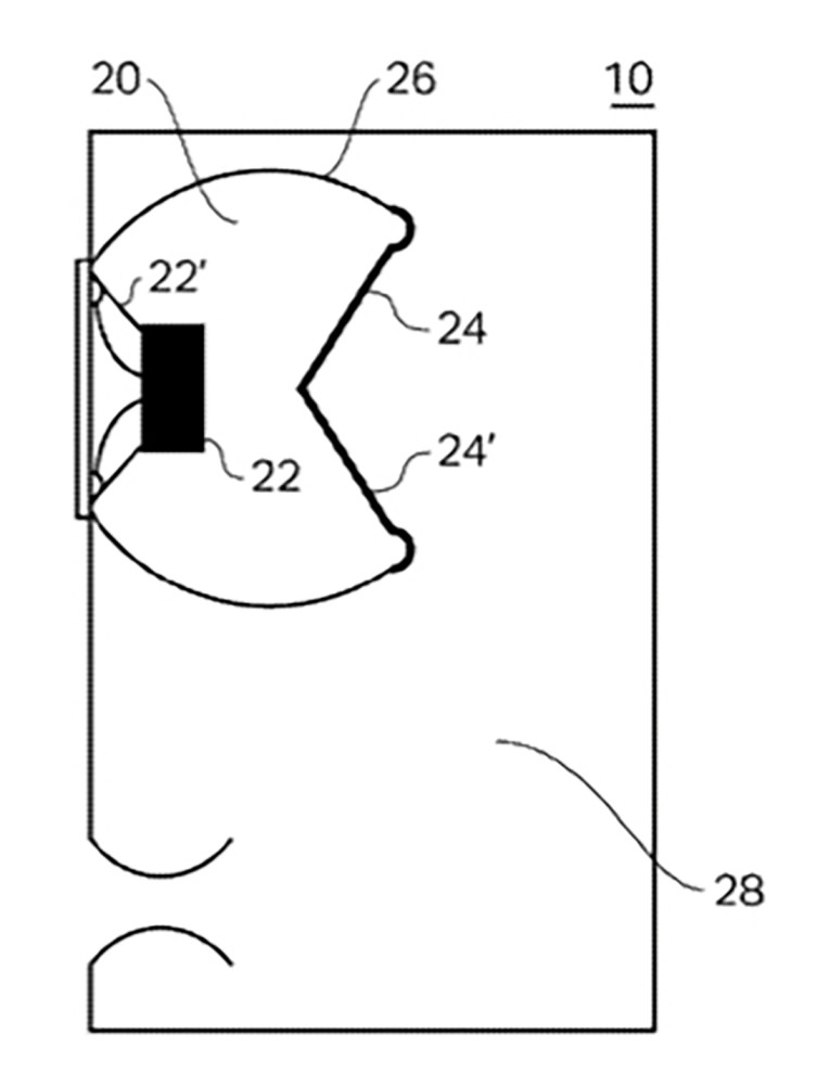
The patent application currently under review discloses a multi-tuned, non-bandpass bass reflex system that is based on the Figure 1a architecture. As can be seen in Figure 2, it is differentiated by the use of a spherical subchamber that is termed as a “sealed acoustic suspension chamber” 26 the sealed acoustic suspension chamber comprising an active woofer transducer 22 and a passive acoustic diaphragm radiator 24 arranged on opposite sides of the sealed acoustic suspension chamber with the active transducer having one surface of its diaphragm radiating to the external environment and the other surface of its diaphragm radiating into the volume 20 of sealed acoustic suspension chamber 26. The output of passive radiator 24 exits into the acoustical compliance of primary internal volume 28, which forms a Helmholtz resonance with the main vent that radiates into the external environment.
The inventor claims a number of benefits of this approach, including:
- The system claims to overturn Hofmann’s Iron Law by allowing one to reduce total enclosure volume, increase efficiency and extend low frequency response beyond the standard limitations of physics.
- It is claimed that the continuously curved shape of the sealed acoustic suspension chamber in combination with a driver, coupled with a passive acoustic diaphragm housed in a sealed acoustic suspension chamber, has the advantage of extending the low frequency response.
- It is claimed that the continuously curved shape of the sealed acoustic suspension chamber in combination with a driver coupled with a passive acoustic diaphragm housed in a sealed acoustic suspension chamber also results in an improved transient response from both the driver and the passive acoustic diaphragm, resulting in more accurate sound reproduction.
- It is claimed that improved transient response causes increased dynamic power handling capability and better operating efficiency.
- It is claimed that when the driver and the passive acoustic diaphragm are integrally arranged with each other, thus forming a tightly sealed chamber, acoustic leaks consisting of pressurized air can be almost entirely avoided. (It is suggested that air leaks are generally a substantial cause of reduced efficiency and acoustic distortion in loudspeaker enclosures.)
- It is also claimed that by making the passive radiator diaphragm 24 larger in surface area than the diaphragm of active transducer 22, transient response is further improved.
- It is further claimed that when the driver and the passive radiator are arranged on opposite sides of a sealed chamber that is substantially spherical, the “internal diffraction” of the rearward propagated sound waves from the driver is dramatically minimized, resulting in an efficient transfer of energy to the passive radiator through pistonic coupling. There are a few more claimed advantages of the design, but since it does not appear that there is any realistic theoretical basis for any of the above claimed advantages, it seems prudent to stop with the first seven.
There seems to be a general misunderstanding of how the components of the system operate. Probably the most interesting characterization is that of calling out the spherical enclosure 26 an “acoustic suspension chamber” when the structure is obviously a standard Helmholtz, bass-reflex resonant chamber with the acoustic compliance of the enclosure volume 20 and the mass of the passive radiator 24 forming a Helmholtz resonant tuning frequency. The system shown in Figure 2 is essentially a dual-tuned bass reflex system, with one passive radiator and one vent. This configuration will realize two advantageous active transducer diaphragm excursion minimums at the two tuning frequencies, and will also exhibit the unavoidable dip in the amplitude response near the upper tuning frequency, as discussed earlier in this review. There is no mention of the advantages of reduced active driver excursion or the disadvantages of an amplitude dip caused by the dual-tuned system.
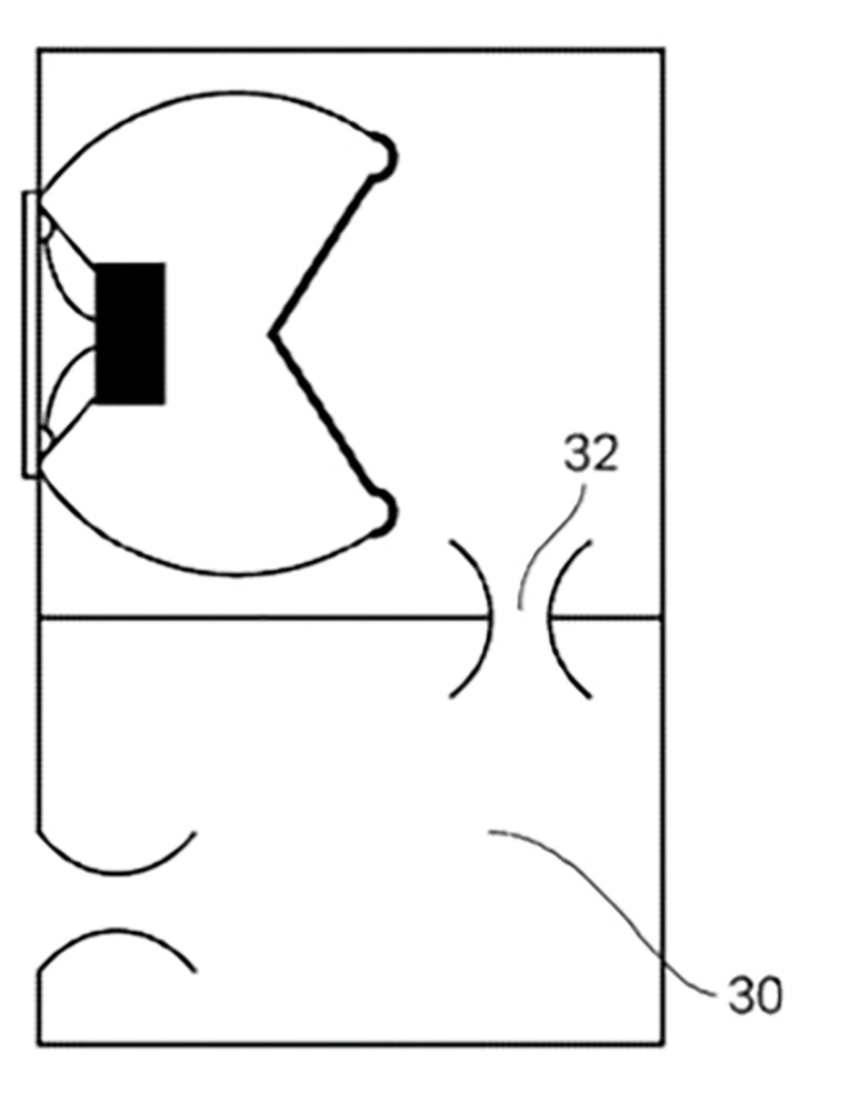
What is actually a more interesting embodiment of the invention is that shown in Figure 3 with the extra internal subchamber and internal vent 32, interacting to create a third tuning frequency. The inventor describes outcome of this embodiment as: “The provision of an optional second band-pass chamber exhibits the properties of a second order low-pass filter, which further extends the low frequency response of the loudspeaker enclosure of the present invention. The optional second band-pass chamber enables improved low frequency response without compromising the overall transient response of the sealed acoustic chamber embodiment.”
Just as a dual-tuned system does not inherently add low-frequency bandwidth to a single-tuned bass reflex system of the same total enclosure volume, a triple-tuned enclosure does not increase low-frequency bandwidth of a dual-tuned system, if all other parameters are held constant. What is gained in each case is the addition of one more excursion minimum frequency. A little known fact is that a significant benefit of a triple-tuned bass reflex enclosure system is that with an effective alignment of parameters, the amplitude dip that plagues all dual tuned reflex systems can be eliminated.
In 1984, a very bright engineer named Robert C. Williamson, while working on new types of system configurations to enhance the large signal capability of low-frequency systems was developing simulation models of a wide variety of low-frequency enclosures types, including tuned pipes, and multi-tuned reflex systems. I was working on the same project and was exploring (among other formats) various forms of full-range and bandpass systems incorporating dual and triple diaphragm, augmented passive radiators.
Williamson’s models (later verified by prototypes) illustrated the large signal advantages of the dual-tuned reflex, but also exposed the same problem of a significant dip in the amplitude response near the upper tuning. His work showed that under high-resolution measurement, the dual-tuned amplitude loss was actually much greater than what was observed by Augspurger and others. Williamson decided to develop a model that combined a single-tuned reflex with the addition of an augmented passive radiator chamber set as a second tuning.
I started working with the model, combining a wide variety of parameter variations but all versions ended up with the same dip in the response near the upper tuning as conventional dual-tuned systems did. At some point, inadvertently, I engaged Williamson’s dual-tuned reflex model along with the augmented passive radiator model. With just a few adjustments to the system tuning parameters the amplitude dip completely disappeared and the overlap of the excursion minimums was deeper and wider than any of the dual-tuned systems.
As we looked at the phase outputs of the active driver and each of the three passive acoustic radiators, we could see that the additional (third) tuning frequency caused a phase rotation that allowed the system to sum all outputs in-phase throughout the low frequency range without any amplitude anomalies. This combined with superior large signal capability resulted in a system that could equal most any other in terms of enclosure volume, bandwidth, and efficiency, but was clearly advantageous in terms of increased low-frequency output capability for a given active driver excursion. As an additional test, the augmented passive radiator was replaced with a standard vent, to end up a more conventional triple tuned system, similar to what is shown in Figure 3 of the invention under review here, and we found that the system continued to show no sign of the amplitude dip of the dual-tuned systems.
So, all this is a long way of suggesting that the triple-tuned version shown in Figure 3 of the current invention, with the correct combination of parameters, has the potential to provide very strong large-signal, low-frequency performance. If the inventor refocuses attention on what the “real” benefits of the invention can be, it should provide significant large signal output advantages over most current systems. VC
This article was originally published in Voice Coil, June 2019