This supposed phenomenon found in two different references [1, 2] would be detected with push-pull (PP) tube amplifiers with output transformers at low levels near our auditory threshold. It would occur for frequencies below 1kHz, where levels were attenuated in a nonlinear way, the effect being most prominent at frequencies around 70Hz.
The first reason for me to do this investigation was because the study was performed with complete PP tube amps, where several non-ideal components such as tubes and non-perfect component matching could additionally contribute to non-linearities, eventually leading to skewed results. That’s why I concentrated on the output transformer (OPT) in isolation.
For that I had two transformers at my disposal, kindly arranged on loan basis by audioXpress technical editor Jan Didden — a toroid VDV-6040 and a VDV-GIT80 with an EI core. The EI is specified at 80W versus 40W for the toroid, but there is no reason why the EI core couldn’t be used as a direct replacement for the toroid, so I will treat them equally. Both OPTs weighed exactly 2.5kg, even though the EI core is specified for twice the power. All I could find about the EI core was that it used a “new high-quality steel,” so I assume this OPT is using Grain Oriented Silicon Steel (GOSS).
The second reason for my investing some time in this was my skepticism about whether a few decibels attenuation, effectively below 200Hz at very low signal levels near our auditory threshold, can be perceived. For convenience I will try to use where possible the same terminology as used in the referenced papers.
Test Setup
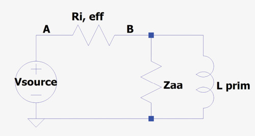
Because the induced magnetic flux from opposite DC bias currents in a PP transformer cancel, I measured from the two outer ends of the center-tapped primary winding without using a bias current. Basically, the simplified equivalent circuit at the primary transformer side looks as shown in Figure 1.
Attenuation at point B is now:

So the lower Ri(eff), the lesser the influence of Lprim will be, ultimately leading to no attenuation at all for a zero Ri(eff). Notice that no Lsp and Csp have been added, but for looking at low frequency first, this will have no impact. Throughout this investigation I will use 5R for the loudspeaker load and 6K for Ri(eff), the latter close to Ri(eff) for a pair of EL34 tubes in super triode mode. Turns-ratio T is 34.3 for the toroid and 32.9 for the EI core selected primary and secondary windings resulting in an expected Zaa of, respectively, 5.8kΩ and 5.4kΩ, that is under the condition that the transformer does a perfect job in transforming the primary to the secondary voltage in a fixed ratio T2 versus frequency, which will be investigated as a first step. With the turns-ratio being quite close for both OPTs, their voltage transfer ratio will differ by less than 0.4dB.
Bode Diagrams
The first step was to measure both OPT Bode diagrams from primary to secondary, loaded with 5R, to find their frequency response and to detect any level dependency with 0Ω Ri(eff). The drive level was either 100mVrms or 1.4Vrms. The results are shown in Figure 2.
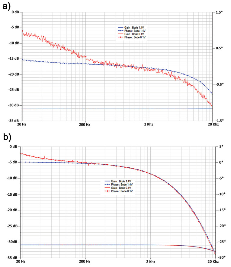
The seemingly noisier phase for the toroid has everything to do with the different scales for the two images, being 3 degrees versus 35 degrees full scale. Zaa will thus be stable at low frequencies because of the OPT level independent transfer, so all possible changes in level can be attributed to a change in Lprim as shown in Equation 1.
Measuring the Primary Inductances
Since Lp = μ0×Np2×A/(lg+lc/μr), where only μr is a variable, changes in level dependent inductance can only be caused by this permeability property.
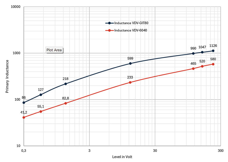
Both OPT primary inductances Lp were specified by the supplier at 230V at 50Hz at respectively 488H and 900H, so to complete the picture, Figure 3 shows the measured level dependency of Lp for voltages all the way down from 230V to 0.3V at 50Hz.

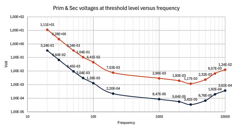
with P(f) the applied speaker power, η being the speaker’s efficiency, d the distance from the speaker and SPL the sound pressure level in decibels according to ISO. Figure 4 shows the voltages on the primary and the secondary at threshold levels, for a speaker efficiency η of 90dB/W at 1m distance. Since primary levels for both transformers are less than 0.4dB apart, only figures for the toroid are shown.
Subconclusion 1
In the reference papers [1, 2] it is stated that “there is a real conflict between the linear signal transfer and the actual mobility of the small magnetic domains.” But looking at the Bode diagrams shown in Figure 2 and Figure 3, there is no sign of it. So far, the decreasing value of Lprim in parallel to Zaa fully explains the OPT attenuation at low levels, as being formulated with Equation 1.
Primary Impedance over the Full Audio Spectrum
Until now we looked at 50Hz because the transformers were specified at this frequency. The next step will be to extend the spectrum from 20Hz to 20kHz. The impedance properties can be analyzed with a vector network analyzer (VNA), comparing the signals between point A and point B, as shown in Figure 1. The graphs are shown in Figure 5.
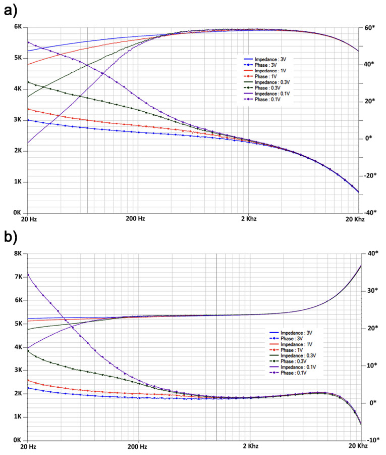
Several things are obviously clear: The expected impedance for the Toroid of N2*5R is only valid for a restricted frequency range, while impedance is also very much level dependent and falls rapidly at low frequency for low level signals. The phase shift of less than 40 degrees at 20kHz for both cores, means a group delay of 40/(360*20kΩ) < 6µsec, which is completely insignificant.
However, the EI core is noticeable less sensitive for low level non linearities at low frequency, where impedance is relatively stable upwards from 150Hz, but then rises significantly starting at 4kHz.
Since the Bode diagram in Figure 2 shows that the direct transfer drops by 2dB at 20kHz, this impedance rise effectively helps to counteract the level drop, as will be seen later.
Deviation from Linear Transfer at Threshold Levels
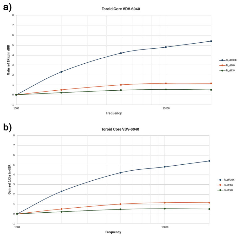
Next, ARTA was used to measure the nonlinear voltage transfer to the secondary 5R at five threshold levels from 30Hz all the way up to 200Hz as indicated in Figure 4, so 66.4mVrms at 30Hz, 9.45mVrms at 50Hz, 3.04mVrms at 70Hz, and so on. Each time a 1kHz signal of equal amplitude was added as a 0dBr reference, since at 1kHz there is no level dependency as was shown in Figure 2. Now comparing the levels of both signals gives the nonlinear deviation at the threshold levels for Ri(eff) values of 3kΩ, 6kΩ, and 30kΩ (Figure 6a and Figure 6b).

Subconclusion 2
At best, our auditory system can detect level differences of 0.3dB. So, let’s assume that this also applies to the low-frequency audio range at low levels. This would imply that the EI core will have an undetectable nonlinear low-frequency behavior for very low levels and plate resistances up to 6kΩ. The toroid on the other hand exceeds this 0.3dB detectable level difference for all three used Ri(eff) values, which could lead to worsened sound perception. When this nonlinear transfer at very low levels is to be held responsible for loss of micro-details, it is obvious that the EI core causes the least of it.
Possible Cause of Loss of Micro Details above 1kHz
Trying to find a clear definition of micro details in audio brought no results; no such definition is provided in the references either; only a possible cause is discussed. But one of the better descriptions found is: “hearing the subtle details in low passages like the breathing of the singer, the musical pages being turned, the decay of a string ….”. These phenomena are usually being noticed somewhere in the higher end of the audio frequency range and not below 100Hz. Because of this I doubt that nonlinearities at low frequency could cause the loss of such micro details.
Again, using ARTA, a multitone signal with 6 lines per octave up to 20kHz was used as Vsource (Figure 1), followed by direct measurement across the 5R load. For the same three Ri(eff) values of 3kΩ, 6kΩ, and 30kΩ, the frequency responses were measured from 1kHz to 20kHz for both transformers. Results are shown in Figure 7.
I have tried to replicate the OPT behavior from 1kHz to 200kHz in LTSpice, by adding measured Lsp and Csp values to the model in Figure 1, but simulations and measurements didn’t even come close. That suggests that there are many different Lsp and Csp instances distributed over many complex layered windings.
Overall Conclusion
Since the frequency response flatness is positively affected by using lower Ri(eff) plate resistances, it could just as well be that perceived loss of micro details is caused by a plate resistance that is too high for these OPTs. Using low plate resistances will kill two birds with one stone; the nonlinearities at low frequency may disappear below the detectable level difference limit and the frequency response will become flatter. Looking at all results shown, it seems that for a PP amp, the EI core would be a better choice, both at the low frequency and the high frequency end of the audio spectrum. Although there is no doubt that the toroid will have a frequency response far beyond 20kHz when driven from a very low Ri(eff), in a real-life situation this ultrasound capability may have little value. aX
References
[1] M. van der Veen, “Low level audio signal transfer through transformers conflicts with permeability behavior inside their cores,”122nd Audio Engineering Society (AES) Convention 2007, Austria, paper 7125.
https://mennovanderveen.nl/index.php/en/develop/10-publicaties/2-low-level-audio-signal-transfer-through-transformers-conflicts-with-permeability-behavior-inside-their-cores
[2] M. van der Veen, “Signal level and frequency dependent losses inside audio signal transformers and how to prevent those,” 130th Audio Engineering Society (AES) Convention, May 2011, London, paper 8360.
https://mennovanderveen.nl/images/onderzoek-ontwikkeling/publicaties/download_5.pdf
Test Equipment Used
Picoscope 16-bits 100MHz 5243B with FRA4PS software to generate Bode diagrams and FRA Impedance viewer to perform the VNA function; ARTA software in combination with a Lynx E22 sound card running on 64 bits W11. Fs set at 96kHz with a 131.072-point FFT giving a bin width of 1.36Hz.
This article was originally published in audioXpress, May 2025


